pcb-tools-extension
===
pcb-tools-extension is a Python library to panelize gerber files.
This library is designed based on [pcb-tools](https://github.com/curtacircuitos/pcb-tools) which provides cool functionality to handle PCB such as generationg PCB image from gerber files.
pcb-tools-extension adds following function to pcb-tools.
- Rotate PCB data
- Write back loaded PCB data (original pcb-tools does not work in some condition)
- Merge multiple PCB data
- Translate DXF file to PCB data
Only RS-274x format and Excellon drill format data can be handled by current version of this library.
## Installation
You can install a stable version by following step.
```shell
$ pip install pcb-tools-extension
```
If you have a intention to try latest developing version, please install as follows.
```shell
$ pip install git+https://github.com/opiopan/pcb-tools-extension.git
```
## How to panelize
Following code is a example to panelize two top metal layer files.
``` python
import gerberex
ctx = gerberex.GerberComposition()
metal1 = gerberex.read('board1.gtl')
ctx.merge(metal1)
metal2 = gerberex.read('board2.gtl')
metal2.to_metric()
metal2.rotate(-20)
metal2.offset(30, 0)
ctx.merge(metal2)
ctx.dump('panelized-board.gtl')
```
```rotate()``` method can be used to rotate PCB data counterclockwise. you have to specify angle in degree.
```offset()``` method can be used to move PCB data. Specified offset values are interpreted according to unit setting of PCB data. In case of the above code, ```board2.gtl``` move to 30mm left since ```to_metric()``` is called.
In case of Excellon drill data, you have to use ```DrillCompositon``` instead of ```GerberComposition```.
```python
import gerberex
ctx = gerberex.DrillComposition()
drill1 = gerberex.read('board1.txt')
ctx.merge(drill1)
drill2 = gerberex.read('board2.txt')
drill2.to_metric()
drill2.rotate(-20)
drill2.offset(30, 0)
ctx.merge(drill2)
ctx.dump('panelized-board.txt')
```
## DXF file translation
pcb-tools-extension hsa a function to load a DXF file and handle that as same as RX-274x gerber file or Excellon NC file.
In this version, Only line, circle, arc, and polyline objects are recognized and are translated to gerber file or NC file.
### Two way to tranlate DXF file
Both composition objects, ```GerberComposition``` for RX-274x and ```DrillionComposition``` for Excellon, can accept an object created as result of DXF file loaded. When composition object dump text stream, DXF data tranclate to appropriate format data.
The object which represent DXF file, can also output translated data directly by ```save``` method. In this case output format is specified by ```filetype``` argument. If ```filetype``` argument is ommited, DXF data is translated to RX-274x gerber data.
```python
import gerberex
dxf = gerberex.read('sample.dxf')
# translate to RX-274x using composition object
ctx = gerberex.GerberComposition()
ctx.merge(dxf)
ctx.dump('sample.gml')
# translate to Excellon using composition object
ctx = gerberex.DrillComposition()
ctx.merge(dxf)
ctx.dump('sample.txt')
# translate to RX-274x directly
dxf.save('sample2.gml')
# translate to Excellon directly
dxf.save('sample2.txt', filetype=dxf.FT_EXCELLON)
```
### Generating Rectangle
If you want to arrange simple rectangle for PCB outline, ```gerberex.rectangle()``` is better solution. This generate a object representing a rectangle compatible with DXF file object.
```python
import gerberex
outline = gerberex.rectangle(width=100, height=100, units='metric')
outline.write('outline.gml')
```
### Drawing Mode
PCB tools extension provide three type of translation method that affects geometric finish. These method are specified a value for ```draw_mode``` attribute, as ```DM_LINE```, ```DM_MOUSE_BITES```, or ```DM_FILL```.
```DM_LINE``` and ```DM_MOUSE_BITES``` are used to translate to both of RX-274x and Excellon, however ```DM_FILL``` is used to translate to only RX-274x.
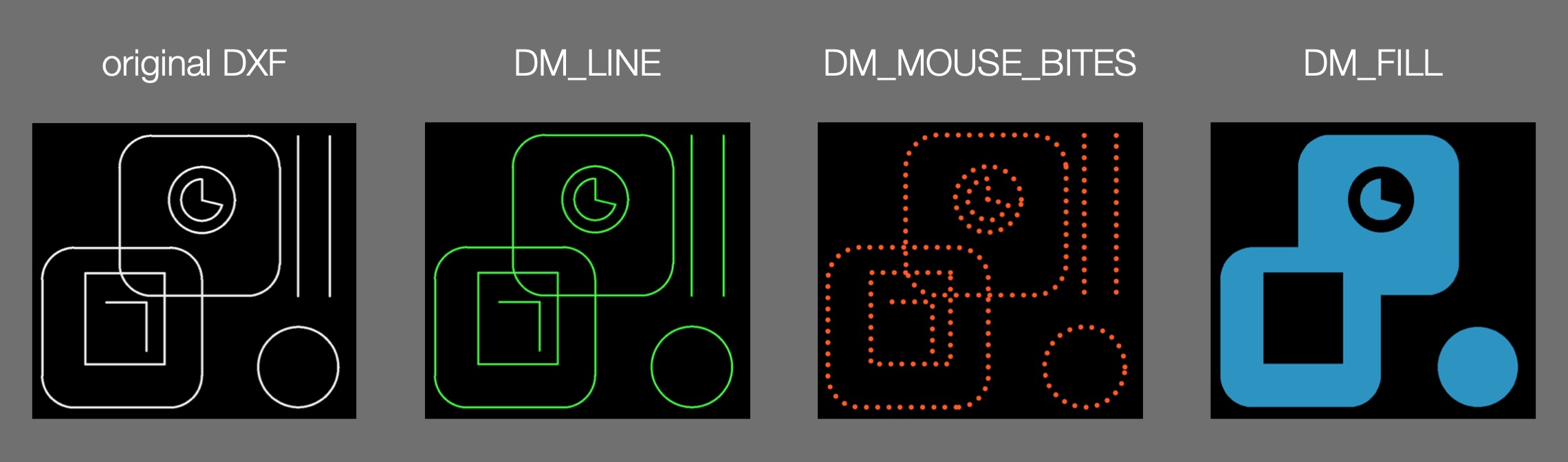
- **draw_mode = DM_LINE**
All edge expressed as DXF line object, circle object, arc object and plyline objects are translated to line and arc applied a circular aperture in case of RX-274x. That circular aperture radius is specified by ```width``` attribute. Default value of width is 0.
In case of Excellon, DXF objects are translated to routing path command sequence.
This function is useful to generate outline data of pnanelized PCB boad.
```python
import gerberex
dxf = gerberex.read('outline.dxf')
dxf.to_inch()
dxf.width = 0.004
dxf.write('outline.gml')
```
- **draw_mode = DM_MOUSE_BITES**
 If DM_MOUSE_BITES is specified for draw_mode, filled circles are arranged at equal intervals along a paths consisted of DXF line, arc, circle, and plyline objects.
DXF file object in this state can be merged to excellon file also. That means you can arrange mouse bites easily.
```python
import gerberex
ctx = gerberex.DrillComposition()
drill = gerberex.read('drill.txt')
ctx.merge(drill)
dxf = gerberex.read('mousebites.dxf')
dxf.draw_mode = dxf.DM_MOUSE_BITES
dxf.to_metric()
dxf.width = 0.5
dxf.pitch = 1
ctx.merge(dxf)
ctx.dump('merged_drill.txt')
```
- **draw_mode = DM_FILL**
If DM_MOUSE_BITES is specified for draw_mode, filled circles are arranged at equal intervals along a paths consisted of DXF line, arc, circle, and plyline objects.
DXF file object in this state can be merged to excellon file also. That means you can arrange mouse bites easily.
```python
import gerberex
ctx = gerberex.DrillComposition()
drill = gerberex.read('drill.txt')
ctx.merge(drill)
dxf = gerberex.read('mousebites.dxf')
dxf.draw_mode = dxf.DM_MOUSE_BITES
dxf.to_metric()
dxf.width = 0.5
dxf.pitch = 1
ctx.merge(dxf)
ctx.dump('merged_drill.txt')
```
- **draw_mode = DM_FILL**
You can translate DXF closed shapes such as circle to RX-274x polygon fill sequence.
In order to fill closed shapes, ```DM_FILL``` has to be set to ```draw_mode``` property. In this mode, All object except closed shapes listed below are ignored.
- circle
- closed polyline
- closed path which consists of lines and arcs
If a closed shape is completly included in other closed shape, The inner shape will be draw with reversed polality of container shape as above example image.
I assume there are two typical use cases for this mode.
One is to arrange logo design on silk layer. This is superior to other method generating raster image data since image data express as vector data.
The other one is generating gerber data represented cropped area of panelized PCB.
By merging rectangle and PCB outline data, generate a file represented cropped area as below, and this kind of data is useful to make PCB image look good a little bit.
[This script](https://github.com/opiopan/pcb-tools-extension/blob/master/examples/genimage.py) which generate example image shown below, also uses this technic.
```python
import gerberex
ctx = gerberex.GerberComposition()
rectangle = gerberex.rectangle(width=100, height=100, left=0, bottom=0, units='metric')
rectangle.draw_mode = rectangle.DM_FILL
ctx.merge(rectangle)
outline = gerberex.read('outline.dxf')
outline.draw_mode = outline.DM_FILL
outline.negate_polarity()
ctx.merge(outline)
ctx.dump('cropped_area.gml')
```
NOTE: ```DM_FILL``` can be used only to generate RX-274x data, it cannot be used to generate Excellon data.
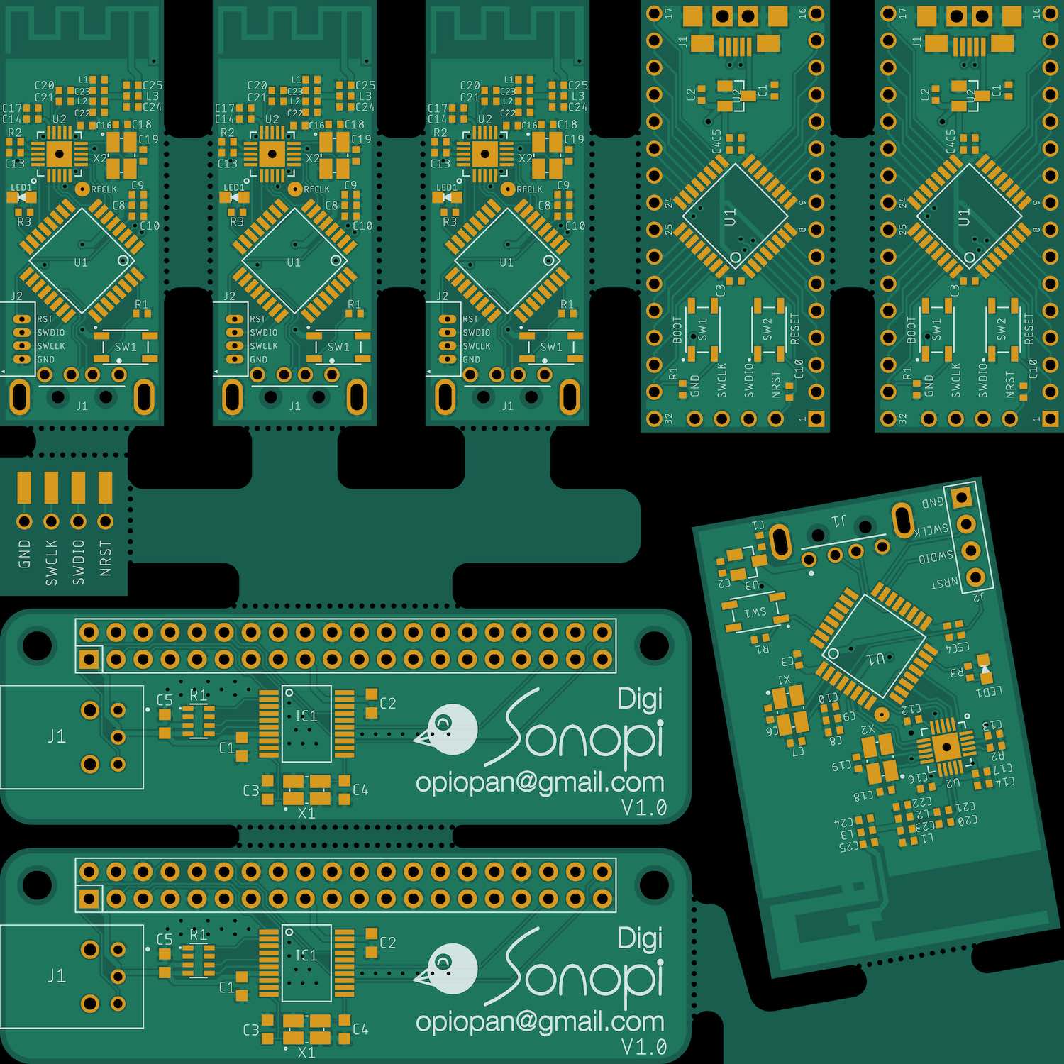
## Panelizing Example
This example board image is generated by following scripts from [these source data](https://github.com/opiopan/pcb-tools-extension/tree/master/examples/inputs).
- [panelizing script](https://github.com/opiopan/pcb-tools-extension/blob/master/examples/panelize.py)
- [imaging script](https://github.com/opiopan/pcb-tools-extension/blob/master/examples/genimage.py)
## Notes
### Equivalence of output
pcb-tools-extension generate data block stream to focus equivalence of final image, but not focus equivalence of data block sequence.
There are some difference between input data and output data as below.
- **Aperture definition [RS-274x]**
When gerber data is rotated, it's necessory to rotate not only coordinates whilch indicate locations of drawing aperture, but also aperture geometory itself.
However, standard aperture templates, such as rectangle, cannot rotate. These standard aperture templates can be placed only horizontally or vertically.
Threfore, pcb-tools-extension replace aperture definitions using standard aperture template to aperture macro that represent equivalent shape.
For example, In case of rotating folowing aperture definition 20 degrees counter clockwise,
```rs-274x
%ADD10R,1X0.5X0.2*%
```
pcb-toolse-extension generate a aperture macro definition and a aperture definition referencing that macro as below.
```rs-274x
%AMMACR*
21,1,$1,$2,0,0,20*
1,0,$3,0,0,20*%
%ADD10MACR,1X0.5X0.2*%
```
- **File Scope Modifier [RS-274x]**
Commands that affect entire image and should be specified only once in a file, such as ```MI``` (Mirror Image) command, sometimes cause contradiction when multiple gerber file are merged.
For example, when mergeing a file containing ```%MIA1B0*%``` command and a file containing ```%MIA0B1*``` command, which command should remain as output?
Of cause, it is impossible that generate correct merged image by specifiing any ```MI``` command.
pcb-tools-extension translate coordinate data reflecting these file socpe modifier to address this probrem, then ommit these modifier command.
```MI```, ```OF```, ```SF```, ```AS```, ```IP```, and ```IR``` are in a this category.
- **Coodinate Normalizing [RS-274x, Excellon]**
RS-274x specification and Excellon specification allow various notation to express a coordinate. However pcb-tools-extension normalize coordinate notation in order to correct deprecated notation and ease internal process as below.
- Relative coordinates are translated to absolute coordinates.
- Ommited coordinate values are compensated.
- Leading zeros are ommited.
- **Single Quadlant mode [RS-274x]**
Cercular interpolation coordinate data in single quadlant is difficult to rotate, because circular arc may pass across two quadlants after rotation.
In order to avoid this problem, pcb-tools-extension change single quadlant mode coordinates specification to multi quadlangt mode.
- **NC controll command [Excellon]**
Form histrical reason, Excellon NC controll format is used to specify drill information to PCB fabricator.
On the other hand, from PCB fabricator point of view, they don't need information other than geometric information, such as drill speed. Because these NC controll sequence doesn't send to NC machine directly, PCB fabricator import customers excellon NC file to their CAD / CAM to pnaelize and check, then they export NC controll data for their NC machine.
pcb-tools-extension ommit all NC command which do not contribute to geometry expression. Specifically, only tool definitions (diametor of drill), tool selections, drilling coordinates, and routing paths are output.
- **Unimportant Command [RS-274x, Excellon]**
Commands not affecting final image such as comment are ommited.
### Negative image polarity
Sometimes, ```%IPNEG*%``` is specified at header of RS-274x file to create negative image.
As mentioned [above](#Equivalence%20of%20output), ```IP``` command is ommited when pcb-tools-extension generate output file. In this case, image polarity is nagated by using ```LP``` command. However this generated file doesn't equal to original image since it does'nt contain base dark image.
Please merge base dark rectangle explicitly when you handle negative image file as below.
```python
import gerberex
ctx = gerberex.GerberComposition()
base = gerberex.rectangle(width=30, height=30, left=-5, bottom=-5, units='metric')
base.draw_mode = base.DM_FILL
ctx.merge(base)
metal = gerberex.read('negative_image.gtl')
ctx.merge(metal)
```
## Limitations
### RS-274x
pcb-tools-extension cannot handle all commands that the RS-274x parser implemented in
[pcb-tools](https://github.com/curtacircuitos/pcb-tools) doesn't handle so far.
From the imaging point of view, pcb-tools-extension has following limitations.
- Files contains ```IJ``` and ```IO``` commands, that affect entire image, cannot be handled correctly.
- Files contains ```SR``` command to specify repeated pattern cannot be handled correctly.
- Aperture block defined by ```AB``` command cannot be handled correctly.
### Excellon
pcb-tools-extension extends excellon parser in [pcb-tools](https://github.com/curtacircuitos/pcb-tools) to support routing operation. However following limitations still remain.
- User defined stored pattern defined by ```M99``` command cannot be handled.
- Canned text specified by ```M97``` command cannot be handled.
- Pattern defined by ```M25``` command cannot be handled.